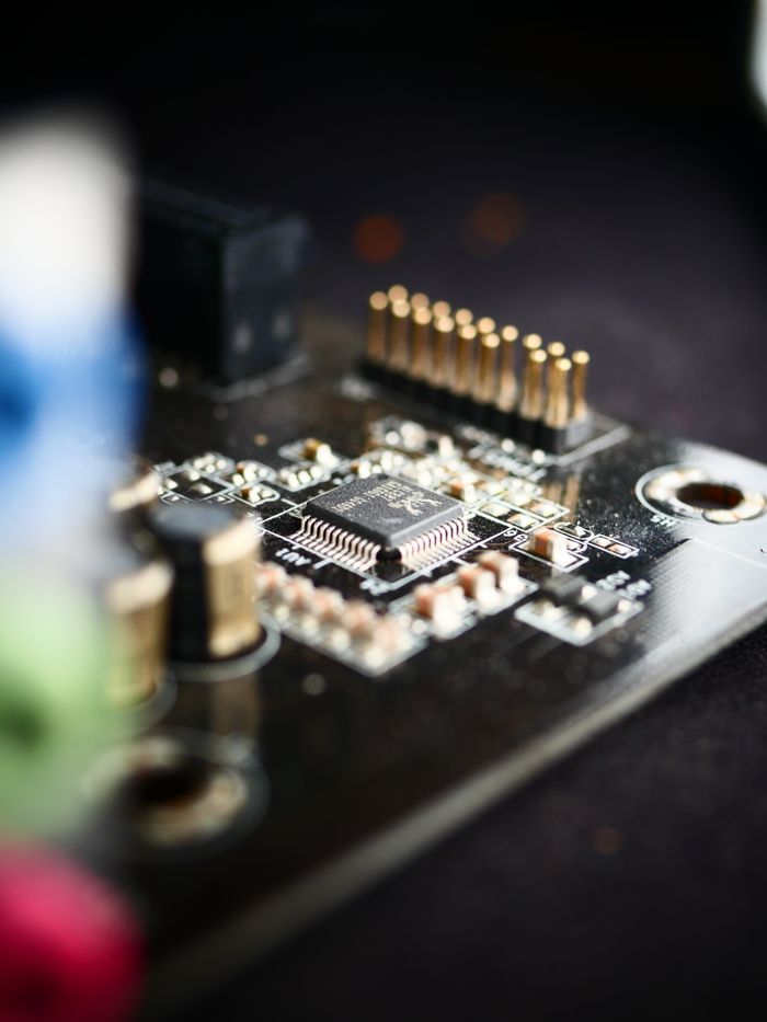





High-Frequency & High-Speed Boards
Full coverage of Rogers, PTFE and low-loss high-speed materials: from RF antennas and mmWave radar to high-speed switch backplanes. Rogers+FR-4 hybrid stack-up cuts cost, with impedance tolerance ±10% (±7% available).
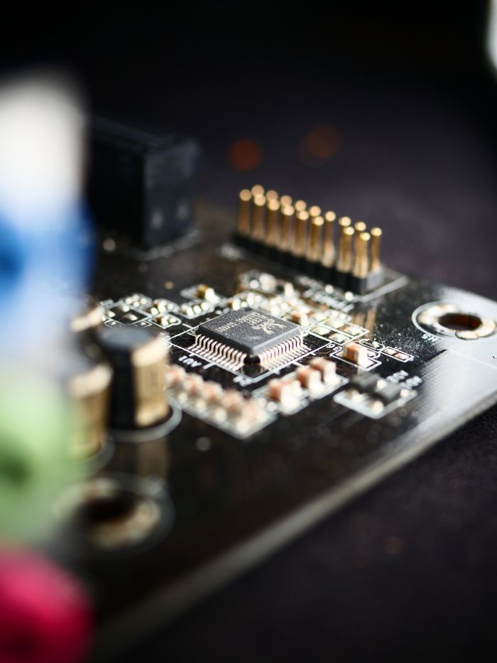
What is a High-Frequency Board
Above several hundred MHz, signal loss on standard FR-4 rises sharply. High-frequency boards use low-Dk (dielectric constant) / low-Df (dissipation factor) materials to preserve signal integrity, while high-speed digital boards focus on low loss and impedance consistency - together known as HF&HS PCB.
| Key Parameters | Stable Dk and lower Df mean less loss |
| RF Materials | Rogers RO4350B / RO3003, PTFE series |
| High-Speed Materials | TU-872 / M6 / Megtron4 and other low-loss laminates |
| Cost-Saving Option | Rogers + FR-4 zoned hybrid stack-up |
| Impedance Control | 50/75Ω single-ended, 90/100Ω differential |
| Typical Uses | Antennas, radar, 5G base stations, optical modules, switches |
Choose Materials by Frequency and Cost
The higher the frequency, the stricter the Df requirement; in the 3-10GHz range a hybrid stack-up can significantly cut cost.
10 GHz
Low-loss FR-4- Df as low as 0.0010
- mmWave-grade loss performance
- Typical: 77GHz radar, satellite, mmWave
Impedance Control & Testing
End-to-end impedance assurance from stack-up design to outgoing test.
| Standard Tolerance | ±10% (50Ω / 100Ω differential) |
| Precision Tolerance | ±7% (after stack-up review) |
| Test Method | TDR sampling with impedance test report |
| Design Support | Free stack-up suggestions and trace-width compensation table |
Hybrid Stack-up: High-Frequency Performance at Lower Cost
Use high-frequency material only in RF routing areas and FR-4 elsewhere - a 10-layer RO4350B+FR-4 hybrid board saves over 50% in material cost versus an all-high-frequency build, the mainstream cost-down approach for antenna and radar boards.
Product Showcase
RF High-Frequency Cases
High-Speed Digital Cases
Manufacturing Capabilities
Standard manufacturing capability range for this product line. Contact our engineers to evaluate special requirements.
| Layer Count (incl. hybrid) | 2 - 20 layers |
| Min. Trace/Space | 4/4 mil (RF area) |
| Min. Drill Size | 0.2 mm |
| Impedance Tolerance | ±10% (standard) / ±7% (after stack-up review) |
| Copper Weight | 0.5 - 2 oz |
| Board Thickness | 0.5 - 3.0 mm |
| Hybrid Stack-up | Rogers/PTFE + FR-4 zoned lamination |
| Surface Finish | ENIG (standard) |
| Impedance Test | TDR sampling with impedance test report |
Lead Time & Pricing Highlights
Signal integrity first
Low-Loss Materials
Rogers/PTFE material systems with Df as low as 0.0010, covering 1-40GHz.
Precise Impedance
±10% standard tolerance, ±7% after stack-up review, with TDR reports.
Hybrid Cost-Down
Rogers + FR-4 zoned stack-up - no performance compromise while cutting material cost by more than half.
Typical Applications
5G Base Stations
Macro/small-cell power amplifiers and antenna array boards.
Automotive mmWave Radar
24G/77GHz front and corner radar boards.
Satellite Communications
Spaceborne and ground-station RF front ends with low loss over long distances.
High-Speed Computing
Switch backplanes, server interconnects and optical module boards.
IoT RF
Wi-Fi 6E/Bluetooth gateways and RF module carriers.
Aerospace
High-reliability RF boards for airborne radar and telemetry links.
From Gerber to delivery in four steps
Upload Files
Send Gerber/ODB++ and stack-up table; standard boards get instant pricing.
Review & Quote
Complex boards get an engineer review before quoting.
Confirm Production
Confirm specs and price, pay online, and your boards enter the production queue.
Test & Deliver
Flying probe/fixture testing on every board with reports, shipped worldwide.
Further Reading
For more PCB process knowledge and technical practice, visit our blog center.